Deep-hole drilling process
TBT has significantly shaped and developed deep-hole drilling technology. In high-performance precision drilling, the single-lip drill has proven itself in practical use thanks to the achievable diameter tolerances and surface qualities, as well as the minimal runout. Therefore, the deep-hole drilling principle replaces drilling and reaming with one operation in a large number of applications and does so with extremely high process reliability.
However, it doesn’t always have to be deep drilled. The combination of precision bore machining and high bore performance has also opened up the field of short and intricate bores to the single-lip drill.
Seal housing method
Submersion method for shallow drilling depths
Deep-hole drilling on machining centres
Deep-hole drilling key data
Seal housing method
Single-lip solid drilling tools in the diameter range from 1.9 mm to approx. 50 mm are used in the seal housing method.
The tool lengths can be up to approx. 6000 mm. During this process, the tools are guided by steady rests. The distance between the steady rests should not exceed a maximum of 40-50 x tool diameter.
The sealing to the machine spindle is achieved by the seal housing or the seal disc inside.
The cutting edge extends over the radius of the bore being produced. The tool consists of a drill head, corrugated shank and the clamping element (sleeve). The conventional single-lip solid drill has a solid carbide head in which the cutting edge and guide pads are ground.
Seal housing method for shallow drilling depths
Single-lip solid drilling tools are used within a diameter range of 0.7 mm to 50 mm. Since no steady rests are used, the drilling depth is limited to a maximum of 160 mm using the submersion method.
This process is particularly suitable for drilling short bores. Solid carbide tools are being increasingly used in diameters between 1 and 12 mm and drilling depths that are not too large. The seal to the machine spindle is made via the immersion sleeve or immersion spindle.
The cooling lubricant is supplied through one or more bores (or kidney-shaped aperture) inside the tool. The coolant chip mixture is discharged via a longitudinal groove (bead) on the outside of the tool shank.
The cutting edge extends over the radius of the bore being produced. The tool consists of a drill head, corrugated shank and the clamping element (sleeve). The conventional single-lip solid drill has a solid carbide head in which the cutting edge and guide pads are ground.
Deep-hole drilling on
machining centres (MC)
In contrast to deep-hole drilling machines, spot drill bushes are very rarely used in conventional machine tools. Therefore, for the use of a single-lip drill, a guide hole must first be made in the workpiece that is to be machined. This bore has special requirements, such as diameter tolerance and guide length.
Any more questions?
Our experts will be happy to advise you on the choice of suitable tools that we manufacture ourselves, e.g. single-lip drills, stepped drills, tools with indexable inserts or solid carbide drills.

Tools
tbttools@tbt.de
T: +49 7123 976-352
F: +49 7123 976-350
Deep-hole drilling key data
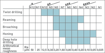
Surface quality
The radial cutting forces that occur are transferred to the bore wall via the guide pads. This results in a press-smoothing of the surface. It can be further enhanced by the design of the guide pad. The result is excellent surface quality.
The result

Diameter tolerance
Bore runout
The drill bushing or pilot bore, which rests against the workpiece, and the hole itself provide the single-lip drill with precise forced guidance, which keeps the runout within minimum limits.

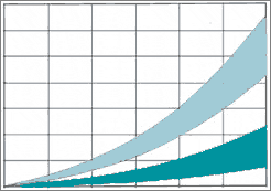
Bore runout reference values
Horizontal axis: Drilling depth in mm
Vertical axis: Runout in mm
Upper graphic: rotating tool
Lower graphic: rotating workpiece
